

-
Step into Capney
400V PQC Industrial Complete Cabinet
- Product Description
- Features & Advantages
- Technical Parameters
- Related manuals
- Figure on the right
400V PQC Industrial Complete Cabinet
-
- Commodity name: 400V PQC Industrial Complete Cabinet
- Commodity ID: 1362032817646227456
- 类型: Industrial automation
- 品牌: Capni
Brand: Zhiyuan New Energy Description: Industrial-grade PQC, featuring a highly efficient power electronic topology and advanced all-digital control technology. It dynamically compensates for reactive current and harmonic current, improves the power factor, and eliminates harmonic currents.
1. Introduction
The Power Quality Compensator (hereinafter referred to as PQC) is an intelligent, active-type new power electronic device developed by our company. It employs a highly efficient power electronic topology and advanced all-digital control technology to dynamically compensate for reactive currents and harmonic currents, improve the power factor, and eliminate harmonic currents.
PQC is a flexible power converter. First, PQC measures the reactive current and harmonic current generated by the load. Then, it generates new reactive and harmonic currents with the same magnitude but in opposite phases, thereby eliminating the vast majority of reactive and harmonic currents in the power supply network. By canceling out the reactive and harmonic currents in the compensation circuit, the following effects can be achieved:
▪ Significantly reduces distortion in the voltage and current waveforms of the power supply network;
▪ Significantly improves the power factor of the power supply system, reduces the design capacity of transformers, and lowers initial capital investment.
▪ Reduce losses in transformers and cables, lower their temperature, and save energy.
▪ Reduce the risk of interference to other equipment caused by system harmonics;
▪ Increase the terminal voltage to improve power quality.
2. Basic Components
The PQC system mainly consists of the main contactor KM1, the pre-charge contactor KM2, the pre-charge resistor R, the filtering inductor L, the voltage-source PWM rectifier bridge (VSR), and the DC bus capacitor C, among other components.
The system diagram is shown in Figure 1. Resistor R serves as the pre-charge resistor for the system. Once KM2 closes, the voltage across the system bus capacitor begins to charge slowly. KM1 controls the main circuit and simultaneously shorts out the pre-charge resistor R. The inductor acts as a power transfer interface between the power converter and the power system; on one hand, it stores energy, and on the other hand, it filters out high-frequency switching ripple currents. The voltage-source PWM rectifier bridge is the power conversion component of the SVG, composed of insulated-gate bipolar transistors (IGBTs). It employs space-vector pulse-width modulation (SVPWM) technology to drive the IGBTs and generate the compensation current waveform. The DC capacitor module stores the DC energy generated by the IGBT power conversion module.
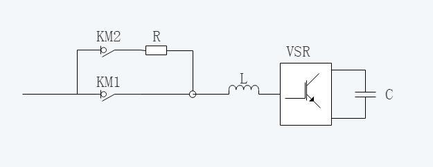
Figure 1: Schematic Diagram of the PQC System
Advanced user experience
Ø The device features a self-diagnosis and self-startup function. It is capable of automatically recovering from a shutdown caused by factors other than device malfunctions. Before initiating self-recovery, the device will automatically diagnose both the external power grid and itself; only after passing the diagnostic test can it proceed with self-startup. If the device attempts self-recovery three times within 30 minutes but fails each time to start up normally, it will shut down and transmit a device failure alarm to the host computer, while simultaneously illuminating its own fault indicator light.
Key words:- 工业型电能质量治理装置
- 工业型滤波补偿装置
- 工业型PQC
-
Design Concept
- Industrial type PQC This product is specially developed by our company for industrial application environments. It adopts a completely new development approach, offering multi-functionality in a single device. Innovatively, it introduces an automatic proportional control mechanism that allows users to freely configure the ratio of harmonic current to reactive power according to different load conditions.
- Active module vertical structure design. This structural model adopts a large-capacity... IGBT Power devices—selecting the effective value for the device. 3 More than double the rated capacity, with ample safety margins to ensure long-term operation even under heavy load and significant impact. The module employs axial-flow fans for heat dissipation, offering high airflow, sufficient air pressure, and excellent cooling performance. The entire cabinet adopts a bottom-inlet, top-exhaust airflow configuration: axial-flow fans at the top of the cabinet extract air, while dust-proof louvers at the bottom allow fresh air to enter. This design effectively isolates the internal components from the external environment, making it particularly well-suited for high-temperature industrial sites and harsh environments—especially those with high dust concentrations. Examples include powder plants, stone-processing plants, tile factories, cement plants, and similar facilities.
Anti-high-voltage distortion
- Applicable to 5%-25% Application of harmonic voltage distortion rate in industrial load distribution systems, with a subtle-level instantaneous response speed and a total response time of less than... 10ms。
Comprehensive compensation, safety and stability
- Harmonic mitigation, inductive and capacitive reactive power compensation—freely select your compensation combination.
- Automatic flow limiting operation and comprehensive fault protection features.
Advanced control strategies and topological structure design
- Adopt LCL Topological structure filtering, when used with output current, does not introduce high frequencies. IGBT Switching harmonic interference is suppressed, and resonance will not occur regardless of the impedance of the on-site power grid system.
Self-diagnosis and self-startup function for faults
- The device is equipped with a self-recovery function that allows it to resume operation automatically after a shutdown caused by factors unrelated to the device itself. Before initiating self-recovery, the device will perform an automatic diagnosis of both the external power grid and the device itself; only if the diagnosis is successful can the device restart automatically. If the issue lies with the external power grid, the device will no longer attempt to start up and will transmit a device failure alarm to the host computer, while also illuminating its own fault indicator light.
Remote IoT monitoring function (optional)
- It can collect data such as three-phase system voltage, current, active power, reactive power, power factor, harmonic content, and harmonic current output from the device, via... GPRS The module is uploaded to the database. Mobile download is supported. APP and web browsing, enabling real-time device monitoring, historical data download, and device startup. / Shutdown and other operations.
-
Input
Rated Voltage (V)
400V AC
System voltage range
±10%
Frequency (Hz)
50/60 ±5%
Wiring method
Three-phase three-wire system
Output and Installation Method
Type
Complete cabinet
Rated Capacity (kvar+A)
75 kVar + 30 A, 100 kVar + 40 A, 150 kVar + 60 A, 200 kVar + 80 A, 300 kVar + 120 A
400 kVar + 160 A, 500 kVar + 200 A, 600 kVar + 240 A, 800 kVar + 320 AIncoming line method
Top-entry/Bottom-entry/Crossbar busbar passing through the top of the cabinet (the cabinet’s incoming cable connection method must be specified in the contract).
Performance metrics
Filter rate
≥90% (within the ordered capacity range and with harmonic content of the load exceeding 30% of the ordered capacity)
Filtering range
2nd to 13th harmonics (if even-order harmonics need to be addressed, please specify when placing the order)
Full response time
≤10ms
Instant response time
≤100us
Dynamic current
1.2x filter rated capacity output, 1 min
Power factor setting compensation
Be equipped with
Inductive or capacitive compensation
Optional
Protection
Overload protection
Automatic current limiting at 100% rated output.
Other protections
Overvoltage protection, undervoltage protection, overtemperature protection
Operating mode
Single-unit or parallel operation
Okay.
Display and Operation
Display interface
7-inch touch screen
Display status
Current, voltage, power, harmonic distortion rate, and more
Operation
Multiple operation mode options, remote or local.
Communication (RS485 interface)
Modbus-RTU features a remote monitoring interface and a backend database, enabling users to conveniently monitor various operating parameters of the device from internet-connected terminals.
Phase Sequence Adaptive
Be equipped with
Environmental conditions
Protection level
IP20 (customizable)
Operating ambient temperature
-10℃~40℃
Storage/Transportation Temperature
-40℃~60℃
Work / Storage Humidity
Relative humidity: 20–95%, no condensation / Relative humidity: 10–95%
Altitude
Below 1000m (reduce capacity for use at higher altitudes)
Get a free product quote
Our staff will contact you within 24 hours (on business days). If you require additional services, please feel free to call our service hotline:0512-50132658
Provide consumers with more solutions.
Power by : 300.cn Beijing | CertificateQuery | File information inquiry | Anti-counterfeiting query